Here are two different diagrams for how to perform a mo.Unit installation on a kick start only motorcycle. Each diagram is a generalized example The wiring for your charging system and ignition probably will not match exactly.
Why are there two diagrams?
Because there are ignitions that rely on power from the battery in order to operate and there are other ignitions that generate their own power.
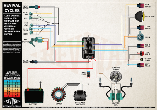
- The first diagram is for older systems with mechanical points, Dynatek systems or Transistorized, TI, TCI Ignition systems.
- The second diagram is for Capacitive Discharge Ignitions (CDI's) and Magneto's.
If you don't know for certain what kind of ignition system you have do not assume that your factory wire diagram is labeled correctly. Due to mistranslations many diagrams that label the ignition module as a CDI are incorrect, and by many I mean most. You can find detailed instructions on how to correctly identify a CDI ignition in the link below.
How to Integrate a CDI Ignition with an m-Unit
FOR MECHANICAL POINTS OR TRANSISTORIZED IGNITION SYSTEMS
Click the image below to open the larger PDF.
FOR CAPACITIVE DISCHARGE IGNITIONS AND MAGNETOS
Click the image below to open the larger PDF.

Hello Max,
Please use our tech support contact form along with any applicable pictures or factory wiring diagrams so we can help you solve your issue.
https://revivalcycles.com/pages/contact
Thanks!
Hi,
On my BMW R75/6 i am installing a m-unit and a R/R. On the diagram above for mechanical point I do not see the starter solenoid. Is this on purpose?
Thanks for your help!
Max
Leave a comment